Whether you’re sculpting a masterpiece from marble or milling a blisk from
titanium, the basic principle is the same: start with a block of material and
remove the unnecessary bits until the target object is all that’s left. Of
course, the details of that process are much more complicated, especially for
5-axis machining.
What is 5-axis CNC Machining?
In the simplest terms, 5-axis machining involves using a CNC to move a part
or cutting tool along five different axes simultaneously. This enables the
machining of very complex parts, which is why 5-axis is especially popular for
aerospace applications.
However, several factors have contributed to the wider adoption of 5-axis
machining. These include:
A push toward single-setup machining (sometimes referred to as
“Done-in-One”) to reduce lead time and increase efficiency
The ability to avoid collision with the tool holder by tilting the cutting
tool or the table, which also allows better access to part geometry
Improved tool life and cycle time as a result of tilting the tool/table to
maintain optimum cutting position and constant chip load
What are the Axes in 5-Axis?
We all know the story about Newton and the apple, but there’s a similarly
apocryphal story about the mathematician and philosopher, Rene Descartes.
Rene Descartes. (1569-1650)Descartes was lying in bed (as mathematicians
and philosophers are wont to do) when he noticed a fly buzzing around his room.
He realized that he could describe the fly’s position in the room’s
three-dimensional space using just three numbers, represented by the variables
X, Y and Z.
This is the Cartesian Coordinate system, and it’s still in use more than
three centuries after Descartes’ death. So X, Y and Z cover three of the five
axes in 5-axis machining.
What about the other two?
Imagine zooming in on Descartes’ fly in mid-flight. Instead of only
describing its position as a point in three-dimensional space, we can describe
its orientation. As it turns, picture the fly rolling in the same way a plane
banks. Its roll is described by the fourth axis, A: the rotational axis around
X.
Continuing the plane simile, the fly’s pitch is described by the by the
fifth axis, B: the rotational axis around Y.
Astute readers will no doubt infer the existence of a sixth axis, C, which
rotates about the Z-axis. This is the fly’s yaw in our example.
If you’re having difficulty visualizing the six axes described above,
here’s a diagram:

(Image courtesy of Hurco North America.)
The A, B and C axes are ordered alphabetically to correspond with the X, Y
and Z axes. Although there are 6-axis CNC machines, such as Zimmermann’s FZ 100
Portal milling machine, 5-axis configurations are more common, since adding a
sixth axis typically offers few additional benefits.
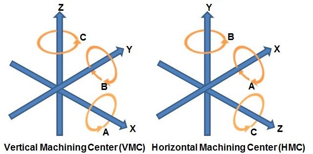
One last note about axis-labeling conventions: in a vertical machining
center, the X- and Y-axes reside in the horizontal plane while the Z-axis
resides in the vertical plane. In a horizontal machining center, the Z-axis and
Y-axis are reversed. See the diagram below:

(Image courtesy of Cameron Anderson/Aerotech.)
5-Axis Configurations
A 5-axis machine’s specific configuration determines which two of the three
rotational axes it utilizes.
For example, a trunnion-style machine operates with an A-axis (rotating
about the X-axis) and a C-axis (rotating about the Z-axis), whereas a
swivel-rotate-style machine operates with a B-axis (rotating about the Y-axis)
and a C-axis (rotating about the Z-axis).

Inside view of the trunnion table of an Okuma MU-4000V 5-axis vertical
machining center. (Image courtesy of Okuma.)The rotary axes in trunnion-style
machines are expressed via the movement of the table, whereas
swivel-rotate-style machines express their rotary axes by swiveling the spindle.
Both styles have their own unique advantages. For instance, trunnion-style
machines offer larger work volumes, since there’s no need to compensate for the
space taken up by the swiveling spindle. On the other hand, swivel-rotate-style
machines can support heavier parts, since the table is always horizontal.
For more information on the benefits of trunnion-style and
swivel-rotate-style machines, check out this pair of videos from Hurco North
America:
Benefits of a Trunnion Table on a 5-Axis Machining Center
Benefits of a Swivel Head on a 5-Axis Machining Center
How Many Axes Do You Need?
You may have seen references to machining centers offering seven, nine or
even eleven axes. Although that many additional axes may seem difficult to
envision, the explanation for such staggering geometries is actually quite
simple.
“When you’re dealing with machines that have, say, more than one turning
spindle, then you already have more axes,” explained Mike Finn, industrial
applications engineering manager at Mazak America.
“For example, we have machines with second spindles and lower turrets. On
those machines, you’ll have several axes: the top turret is going to have 4 axes
and the lower turret has 2, then you have opposing spindles that have 2 axes as
well. Those machines can have up to 9,” Finn continued.

Mazak's INTEGREX i-400ST. (Image courtesy of Mazak.)“The parts you’re
making are still 5-axis parts,” added Wade Anderson, product specialist sales
manager at Okuma America.
“A component, like an aerospace valve might be done on our MU-5000 vertical
center, which is a 5-axis machine. Or we could do that part on a multi-axis
machine that has a rotary B-axis and twin spindles for two C-axes, plus X, Y and
Z. There’s also a lower turret that gives you a second X and Z. So it gives you
more axes, but the part itself is the same geometry,” Anderson explained.
So how many axes do you need?
As is often the case in manufacturing, the answer to that question hinges
on your particular application. Finn gave the following example:
“A turbine blade is a freeform surface and can be rather complex. The most
efficient way to finish machine a blade like that is to use 5-axis, taking the
tool in a spiral around the airfoil of the blade. You can use a 3-axis to
machine if you index the blade to a position and then use three linear axes to
surface machine it, but that’s typically not the most efficient way.”
Anderson agrees: “The geometry of the part will tell you if you need a 3, 4
or 5-axis configuration.”
Okuma's MU-6300V 5-axis vertical machining center. (Image courtesy of
Okuma.)However, it’s important to remember that the number of axes you need
depends on more than just one part. “The part will dictate a lot of it, but then
there’s also what the shop wants to accomplish,” said Anderson.
“A customer might bring me a part, say a titanium aerospace bracket, and I
might say, ’That’s a perfect part for a 5-axis machining center,’ but they might
be planning on making parts that would work better on one of our MULTUS U
machines. That multi-function machine might not be optimized the same way a
5-axis machining center is, but it may give the customer opportunities for doing
lathe, shaft or chucker work that’s part of their long-term plan.”
“Another thing to consider is the work envelope,” Finn added. “What’s the
maximum size part that you can put in the machine and still perform tool changes
and part transfers? It’s understanding the machine’s capabilities and what it
can and can’t do.”
Why use 5-Axis Machining?
Trying to decide between 3-axis machining and 5-axis machining is a bit
like trying to decide between having a MacDonald’s Quarter Pounder or a T-bone
steak; if cost is your only concern, then the former is obviously the way to
go.
However, the dilemma becomes much more complicated when comparing 5-axis
and 3+2-axis.
5-Axis vs 3+2 Axis
It’s important to distinguish between 5-axis machining and 3+2-axis
machining. The former—also called continuous or simultaneous 5-axis
machining—involves continuous adjustments of the cutting tool along all five
axes to keep the tip optimally perpendicular to the part.

Full 5-axis demo part made from 6010 Aluminum on a DMG MORI DMU50. Cycle
time: 13 minutes. (Image courtesy of the author.)
In contrast, the latter—also called 5-sided or positional 5-axis
machining—involves executing a 3-axis program with the cutting tool locked at an
angle determined by the two rotational axes. Machining that involves reorienting
the toolbit along the rotational axes between cuts is called ‘5-axis indexed’
though it still counts as 3 + 2.

3+2 axis demo part made from 6010 Aluminum on a DMG MORI DMU50. Cycle time:
7 minutes. (Image courtesy of the author.)The main advantage of continuous
5-axis machining over 5-axis indexed is speed, since the latter necessitates
stopping and starting between each reorientation of the tool whereas the former
does not.
However, it should be possible to produce the same results whether using
continuous or indexed 5-axis. (Readers who disagree are encouraged to share
examples of parts that can only be machined with continuous 5-axis in the
comments section below.)
It’s also worth noting that with the speed advantage comes more moving
parts, which leads to increased wear and tear as well as a greater need for part
crash detection. This is one of the reasons continuous 5-axis machining is more
difficult from a programming standpoint.
5-Axis Machining vs 3D Printing
3D printing—or additive manufacturing—is a hot topic in the manufacturing
world right now, especially as it compares to subtractive manufacturing
processes like 5-axis machining.
Although it is sometimes suggested that these two methods are in
competition—with die-hard 3D printing fans arguing that the technology will soon
disrupt the entire manufacturing industry—the more moderate view takes additive
and subtractive manufacturing to be complementary processes.

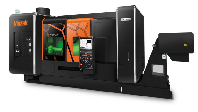
Mazak's INTEGREX i-400AM combines additive manufacturing and 5-axis
machining. (Image courtesy of Mazak.)“I don’t think additive manufacturing is
going to completely take over, but I do think there are opportunities to design
parts that couldn’t have been designed in the past,” said Finn. “But there are
still parts that require subtractive machining. For example, parts that have a
really tight circularity tolerance.”
“It’s possible to grow a feature to a near-net shape, but that feature may
still need to be machined to achieve the proper tolerance,” Finn added.
Does that mean the future of manufacturing will be a hybrid 3D
printer/5-axis CNC—maybe with a coordinate measuring machine thrown in for good
measure?
Anderson isn’t so sure: “The real world application [of 3D printing]
outside a laboratory environment is not having a combined style machine, but
[for example] having a laser deposition machine do what it does best, having a
turning or milling machine do what it does best and combining the two through
automation.”
The reasoning behind having two separate machines comes down to powder and
chip management.
“The amount of powder you flow in laser deposition to make a 30-pound part,
for example, could be 150-300 lbs of titanium,” said Anderson. “If that goes
into a machine where everything is combined, there’s not a good way to reclaim
all that powder.”
In other words, questions regarding the relationship between 3D printing
and 5-axis machining are less often about competition than cooperation. “I think
additive manufacturing may reduce the amount of roughing that needs to take
place,” Finn concluded.
How to Get the Most from 5-Axis Machining
It’s not uncommon to see 5-axis capabilities being under-utilized.
“Some may have the machine but not understand it’s full capability, or they
may not have the software that’s needed to create a cutting program that would
utilize the machine’s full capabilities,” Finn observed.
Anderson agrees: “That’s a heart-breaker for companies like ours; when we
see a company that goes all in, gets a piece of equipment, they put it on the
floor, and then for various reasons they take a multi-function machine that has
5 or more axes and they use it like a 3-axis machine. It happens all the
time.”

Diagram of the Okuma MU-10000H horizontal machining center. (Image courtesy
of Okuma.)“A lot of that is personnel,” Anderson added. “It’s training and
understanding how to utilize the machine. Sometimes it’s difficult for them to
think about processing this part with an upper turn, a lower turn, a main
spindle and a sub-spindle, all in the process at one time. It’s
overwhelming.”
“There are a lot of software companies that are getting a lot better at
being able to do that type of thinking for you, but it is tough,” Anderson
concluded.
The Importance of 5-Axis Controls and Software
Although having a machinist with the right skill set is a major contributor
to maximizing a 5-axis machine’s capabilities, the machine’s control and
software are just as important.
“When you’re doing high-speed 5-axis machining, the servo drives on the
machine and the response time is very important to avoid shortcutting or
overshooting when machining,” said Finn. “The controller in the machine has to
be able to process the data fast enough so the toolpath is a nice, smooth,
uniform motion. You don’t want jerky motions that could cause gouging.”

Mazak's MAZATROL SmoothX CNC. (image courtesy of Mazak.)
“Likewise, the software that creates the 5-axis programs has to be able to
create nice smooth code so the machine can move in that smooth motion,” Finn
concluded.
Choosing the right CAD/CAM package is essential to getting the most from
your machine.
“If you’re doing aerospace blisks, for example, you need to be working on
the high-end packages,” said Anderson. “If you’re just making small aluminum
widgets for a die cast component for an automotive company and all you’re doing
is drilling a couple of holes on an engine case, that’s a completely different
story.”
“If you are cutting parts that require a CAM system to generate cutting
programs, you should invest in a CAM system that complements the machine’s
abilities,” Finn added.
Avoiding Collisions in 5-Axis
When it comes to creating 5-axis toolpaths, there is generally a trade-off
between running at higher speeds and feeds and minimizing the risk of crashing.
Fortunately, there are a number of software tools on the market today that can
help eliminate that.
“With our collision-avoidance software, you can load a 3D model of the part
and the tools, and the program looks ahead of every move the tool makes to see
if it’s going to run into anything,” said Anderson. “Provided your fixture is
modelled correctly, it will catch the collision before it happens.”

Okuma's Collision Avoidance System working in real time. (Image courtesy of
Okuma.)
“There is software out there that will do machine simulation,” Finn
commented. “So that is important, especially on your high-dollar parts. You
don’t want to have any type of collision that would cause you to scrap a part,
cause someone to get injured or damage the machine.”
“Vericut offers 3D virtual monitoring software that will do the same thing,
only on an offline computer,” added Anderson. “So instead of running in real
time on the controls, you run your part program through Vericut and it will
check all your toolpaths and verify that it’s going to do what you think it’s
going to do.”
5-Axis Tool Sensing
High productivity is a benefit of 5-axis machining, but it also increases
the risk of errors, such as using a broken tool or the wrong tool. One way to
minimize these errors is to opt for a tool-detection system, such as this BLUM
laser on the DMG MORI DMU 50:
A DMU 50 featuring a BLUM laser detection system.
5-Axis: Done in One?
The notion of ‘Done in One’ is a lofty goal in manufacturing: you load a
block of material into a machine, run the program and remove a completely
finished part. Like having zero setup time, the done-in-one goal is worthwhile,
even if it’s ultimately unattainable.
That being said, 5-axis machining gets us closer to the done-in-one goal
than any other process; even 3D-printed parts require finishing. In this
context, a major constraint on 5-axis machining is workholding.
“So much of 5-axis work revolves around the workholding,” said Anderson. “I
can have the best machine in the world, but if my workholding is lousy, I’m
never going to have the part that I want at the end of the day.”
According to Finn, the key to getting around this bottleneck lies in
utilizing machines with more than five axes:
“For example, our INTEGREX machine can be equipped with opposing turning
spindles and a lower cutting turret. So parts can be cut on one spindle and then
transferred to the opposing spindle to machine the remainder of the part. So in
essence you can load in a piece of raw stock and then unload a finished
part.”
The Art of 5-Axis Milling

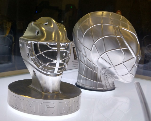
5-Axis demo parts. (Image courtesy of the author.)5-axis machining offers
significant benefits, including reduced lead time, increased efficiency and
improved tool life. However, it’s important to recognize that attaining these
benefits requires more than just purchasing the latest 5-axis machining
center.
Mastering the art of 5-axis necessitates taking a host of factors into
account. On that topic, Anderson said this:
“When you look at problems that customers have, very seldom is it machining
a part. Typically, the problem that’s holding them back is centered around
something other than making a chip. It’s training, it’s having personnel, having
communication go correctly from the routing to the machine or knowing before
they get started that they’re going to have enough tools in the magazine to
finish the part when they start on it. The peripheral parts of the business hold
them back more than actually making the part.”


